Overview
Here is a YouTube video explaining some of my test techniques briefly as well as a more in depth look at how I test USB-C PD chargers.
12V 2A-20A Test Load
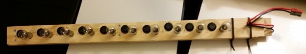
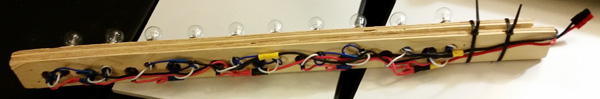
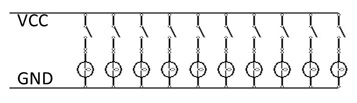
To create this test-load I mounted 10 type 1156 incandescant car tail-light bulbs and switches in a piece of scrap ply-wood to hold them in place and then attached an Anderson PowerPole for easy connection to various power sources. This provides a variable load from 2A to 20A in 2A intervals. The design is extremely simple, each bulb is approximately 2A at 12V and has it's own on-off switch. An ammeter can optionally be connected between the load and the item under test.
Use-Case -- The most common use I have for this load test rig is for "longer" tests, such as testing a battery's capacity or verifying a power supply can provide the expected output for an extended time period. While doing this I frequently connect a PC-logging multi-meter to plot the voltage over time so I can later draw additional conclusions from the voltage-curve (such as sagging after an extended time or determining how long a battery is useful before it will drop off). A less common use is for calibrating pieces of wire used as current-shunts by applying a known-load and computing the resistance of the shunt so I can take accurate current measurements on other unknown loads with my meter or as an input to a programmable micro-controller.
Operation -- The operation is very simple, the test-load is connected to a power source optionally thru a meter. The desired number of bulbs are then turned on until the required current is being drawn (about 2A per bulb so 5 bulbs for a 10A draw). The voltage is then monitored for the duration of the test.
General-Purpose Low-Current Test Load
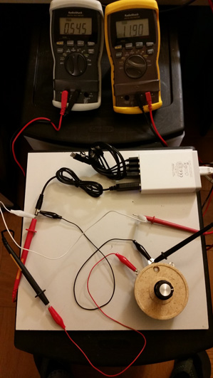
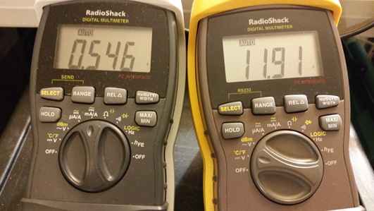
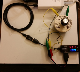
For testing lower-power supplies and solar-panels, I needed to have a more adjustable load test rig. In the photos above I am testing a USB to 12V boost converter, I have determined it will put out around 550mA (measured on the left meter) at "close to 12V" (measured on the right meter) reliably. Unfortuniately this particular adapter was rated for 800mA output but now I know what it can actually do and at what threshold the voltage sags - in this case it isn't shown but a bit over 600mA it begins to drop significantly and becomes unstable.
In order to do this, I purchased a couple of high-power rheostats (10-ohm, 50W and 100-ohm, 100W) that are fairly good size. Depending on the supply voltage this allows me to adjust the load over a wide variety of values. At 12V I can adjust from about 150mA to about 3A or for 5V supplies I can adjust from about 50mA to 3A depending what I am testing. Usually I connect these with jumper test-leads although one day I may put them in some sort of enclosure. You may have noticed I said the rheostats are rated at 50W and 100W but I said I only measure up to about 3A at 5-12V, that's a whole lot less than 50-100W.
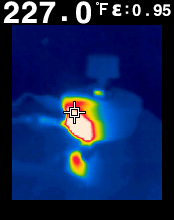
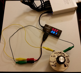
This picture iullistrates why I stay so far under the rated power - the resistive load dissipates all the energy as heat -- even well under the rated wattage it gets HOT. This particular photo was taken while testing a 5.02V power supply (USB) at 2.81A for only a couple minutes, the portion of the rheostat that was dissipating the energy got hotter than boilling water even at just 14.1W, well under it's 50W rating. The resistance of the coil in the rheostat for that works out to 1.8 Ohms or about 20% of the whole 10-ohm resistive coil being "used" in the test. The over-size rating helps it cool faster but you also need to be aware of how hot it's getting and how long you are running the test. to not burn yourself or anything else. The smaller red spot in the photo below the large white area is a reflection of the heat off the ceremic floor tile I use for a work surface. The tile cost under $1 at the hardware store and is highly heat-resistant so I can even solder on it with a small torch without damaging my plastic shelf it's sitting on.
Use-Case -- The most common use I have for this load test rig is for determining actual specifications and useful-output of small power supplies, up/down converters, portable solar panels, and other light-duty items. In some cases it is also useful for testing low-power supplies to verify they don't sag or overheat over longer periods of time.
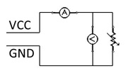
Operation -- typically I will connect the meters as indicated with the resistance set to it's maximum position. I then slowly turn the resistance down whie observing the voltage and current. I continue decreasing the resistance (being sure not to go all the way down to a short-circuit) until I observe either a 5-10% drop in voltage from spec or reach the maximum rated current. Then I record both voltage and current (thus determining the actual useful ratings) and optionally wait for 10-20 minutes of observation to verify nothing overheats or drops off while operating at that current for an extended time.
USB Cable Test Rig
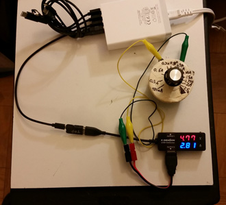
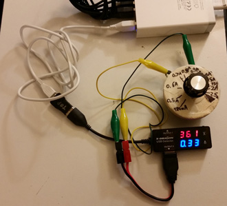
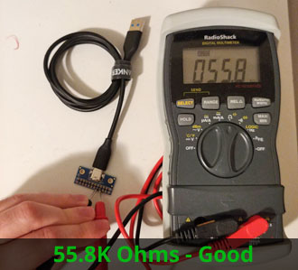
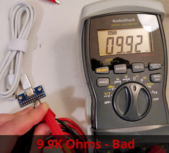
This project started out of frusteration with some of my USB devices inexplicably taking a really long time to charge or refusing to charge with some combinations of cables and chargers. I eventually determined that some cables worked better than others and wanted to find a way to quantify and predict which cables are "good" (pictures 1 and 2) and which cables are "bad" (picture 3) and identify the un-named specifications. To do this I used a simple variable resistive load to increase or decrease the current while monitoring the voltage at the "far end" of the cable. My current favoriate micro-USB cables are by a company called iXCC available on Amazon, while they look rather flimsy they have really surprised me with their exceptional performance for the cost of the ones I have tested so far. The cable in my photo that performed badly I don't know the brand of, I think it came from either a random eBay purchase or a friend's "not working right" phone charger and now serves as my demonstration not to judge a cable by it's appearance - the "really bad" cable actually looks far nicer (thicker and with strain relief) than the "really good" cables I have.
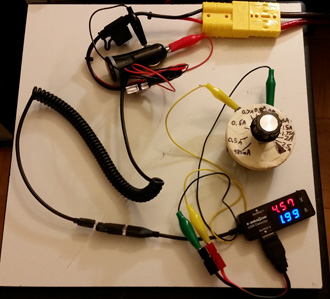
It's also worth noting, although they are not "cables" per say this same method works to test car-chargers and wall-warts with "perminantly connected USB cables" as shown by my photo above (the exceptionally well performing now-discontinued Rocketfish brand Kindle tablet charger). In this photo I'm supplying it with 13.8V DC (simulating a car with engine running) from a bench power supply (the thick yellow-plug cable) and then using the USB cable test setup to measure the voltage at it's rated current from the micro-USB connector.
Before being able to conduct any useful tests on a cable, the power supply must first be tested and proven to provide at least the desired test-current while not dropping in voltage. It should also put out 5.0V and not some arbitrarialy higher voltage like 5.3V (which may skew the results). My current preference is to use an Anker 60W 6-port USB power hub which I have observed puts out 5.0V up to nearly 3A on a single port without dropping any measurable voltage (as demonstrated in the photo above). The test is essentially following the "General-Purpose Low-Current Test Load" above, using a 10-ohm rheostat.
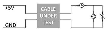
Once the power supply is proven to be reliable and able to put out the required current at the expected voltage, I connect the same test rig to the "far end" of a USB cable. While I could perform the test simply measuring the voltage at both ends I feel that this method of measurement better represents what a device would "see" being connected to the charger which is a more useful real-world test. Once again, the test follows the same process as the "General-Purpose Low-Current Test Load" above, except measuring at the device-side of the USB cable.
Use-Case -- This test allows you to determine the specifications of a particular USB cable. Most cables I have seen simply advertise things like "fast charging" without really saying what that means. By performing these tests, I can "rate" a cable and ensure it will provide at least the maximum power a particular device may draw. For example, when fully drained my smartphone draws 1.75A on the OEM cable and OEM charger but some aftermarket cables provide as little as 200mA before they drop significant voltage. I want to ensure any cable I might use to charge it will perform optimally and therefore test to provide at least 1.8A while maintaining 5V at the device-end of the cable.
Operation -- I connect the USB cable to the charger and then connect my meter and load-test rig to the device-side of the cable using an appropriate adapter if neccesary. I currently have adapters (from Amazon) for mini-USB Female to USB-A Female; micro-USB Female to USB-A Female; and now finally a combination of adapters for USB-C Female coupler + USB-C to USB-A Female. As with the other tests, I start with the highest resistance and continue turning the resistance down until I reach "almost 3A" (which was proven to be the maximum my particular charger will put out at 5.0V) or until I see the voltage drop to between 4.75V-4.5V (5-10% drop). I then record the voltage and current being passed by the cable as the maximum this particular cable will support.
Important note about USB-A to USB-C Cables
You may have read about these cables being dangerous in the news. I have based my tests on a subset of the tests outlined here and the chart showing resistor values for current rattings I found here.
Cables that go from USB-A to USB-C such as those often used for smartphone charging or data-transfer have an additional test that should be done besides basic voltage/current wiring specs. Even if the wiring is correct, these use a resistor in the USB-C plug to tell the device what the maximum power draw thru the cable should be. Unfortuniately, some cables are non-complient and as a result they could cause damage to some devices if they are used. The pictured cable that has an improper resistor value came with a BatPower charger, though the charger itself seemed fine when used with a compliant cable.
Certainly there is always the risk of damaging test equipment (such as the USB-meter) or the test-charger with a faulty cable but my goal is to test the cables on things that are more easily (and affordably) replaced before putting them in service on expensive devices I care about. It would be frusterating to destroy $50 worth of chargers and meters but it would be a lot worse to destroy hundreds of dollars of computers, phones, etc.
Measurement -- with the cable UNPLUGGED from power, test with an ohm meter between pins A4/A5 and B4/B5 of the USB-C connector (Note - A4/B4 may be labeled "V" or "V+" on some breakout boards). One should be open-circuit, the other should be around 50-56K-ohms. If it measures around 10K-ohms the cable should not be used.
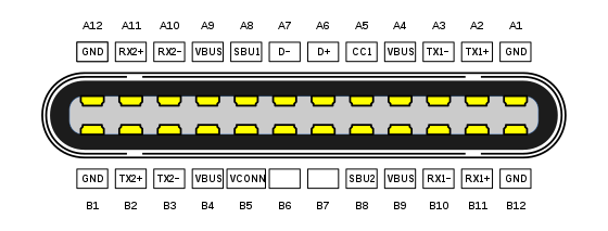
The pinout for a USB-C connector is above for reference.
USB-C PD (Power Delivery) Charger Testing
Testing USB-C Power Delivery is different and more difficult than normal USB because it involves a "handshake" to enable the different higher power outputs which are controlled by a microprocessor. Fortuniately, there is a small development board called "PD Buddy Sink" which has the required software to easily interact with USB-C PD supplies. Using this in conjunction with the PD Buddy Wye you can connect a computer terminal to a PD power supply and perform a variety of tests and collect a significant amount of information.
Typically, I follow a fairly simple test procedure:
- Verify the basic 5V profile works using the methods above
- Connect the PD Buddy Sink to the PD Buddy Wye combined port
- Connect the "DFP" port of the Wye to your computer (you will also need console software such as PuTTY or Screen)
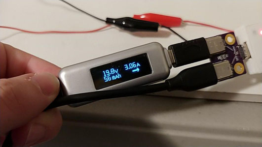
- Hold down the "config" button on the Buddy Sink and connect the charger/power supply to the "Power" side of the Wye thru a USB-C power-meter
- After a few moments, open up the correct serial port on your computer to connect to the PD Buddy. On my Linux computer, I use the command `screen /dev/ttyACM0`
- Press enter and you should get a prompt `PDBS)` on your screen
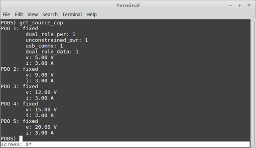
- I begin by checking what power-profiles are supported according to the PD chip with the command `get_source_cap` and compare this to the advertised specifications
- Next, I connect a load with sufficiently high resistance and wattage to support the highest profile to the output of the PD Buddy Sink board
- Now I enable the power output by specifying `output enable`
- For each of the power outputs, I configure the voltage (mV), current (mA), and test it with a load.
E.g. to test 20V 1.5A I would input the following commands (without quotes/backtick):
`set_v 20000`
`set_i 1500`
`write` - Now follow my test procedure for general load test -- decrease the resistance while monitoring a USB-C meter until you verify it meets the advertised load or drops to unreasonable low voltage (I use 10%)
- Return the resistance to maximum or disconnect the load and repeat for each of the remaining voltage profiles.
Additional documentation about the PD Buddy Sink is available on GitHub maintained by its maker.
USB QC (QuickCharge) Testing
At this time I do not have a method to test the higher power levels of QC chargers. The base 5V level can be tested the same as any other standard USB supply.
Resources and Links
Meters & Test Devices
- USB-A LED Readout Meter (use top port for QC)
- USB-A OLED-LCD Meter
- USB-C Meter (works with PD and QC)
- USB-C PD Buddy Sink power board by Clayton G. Hobbs for DIY power projects and interfacing PD power supplies
- USB-C PD Buddy Wye by Clayton G. Hobbs for connecting PD Buddy Sink to power-supply and PC to perform testing
Adapters
- mini-USB Female to USB-A Female
- micro-USB Female to USB-A Female
- USB-C Female coupler (NOTE - seems to only work one way, rotate one connection 180 degrees "upsdide down" if it does not work)
- USB-C to USB-A Female
- USB-C Extension (e.g. to fit meter around narrow cases and close ports)
- USB-C Connector Breakout
Cables I like
- iXCC micro-USB Cables
- 9ft USB-C USB-C Cable (great for laptop chargers)
- 3-Pack USB-A to USB-C 3ft cables
- 2-pack micro-USB to USB-C adapter for legacy cables/chargers (includes tether)
Chargers I like