Echolink Node
This uses a Raspberry Pi, USB-sound-card, and a few DIY cables to connect to a transciever for a simple Echolink node. Note, once you get it installed with my scripts, you will need to refer to the Svxlink documentation for details on configuring it, the exact details depend on a lot of things including what you want it to be (simplex or repeater, what kind of radio, etc) so I can't easily build a guided script for everything. Svxlink is an extremely powerful tool, it does a lot more than Echolink but the Echolink function is my main use for having it personally.
System requirements:
- Reliable internet connection
- Raspberry Pi
- Compatable USB-sound-card
- Ground-loop isolator filters or audio transformers (for mic/speaker interface)
- Some circuitry to interface PTT from 3V TTL GPIO on the Pi to whatever works your radio
- Ideally, also some "carrier-detect" output from the radio, and a 3V level shifter circuit to tell the Pi when a signal is coming in (VOX type detection is possible but less reliable)
Software
The setup scripts are documented on my GitHub page, https://github.com/mmiller7/svxlink-rpi-setup. Once installed, there is still a fair bit of setup and tweaking to do for the Svxlink configuration to get it "talking" to the radio and logged into the Echolink servers. There is a sanitized version of my svxlink config on my GitHub page under sample_configs. For the full details, you should read thru the svxlink documentation on their official site.
Here are the features my sample config demonstrates:
- svxlink.conf -- set up for simplex-node radio control using GPIO
- svxlink.conf -- commented out settings for repeater, TX radio using GPIO, RX radio RTL-SDR
- ModuleEcholink.conf -- settings for up to 10 incoming connections and running thru private proxy
- default/svxlink -- the GPIO pin configuration for PTT/COS
- TCL files -- modification to eliminate beep on Echolink start/stop
- TCL files -- added enable/disable DTMF commands (toggled via DTMF)
- TCL files -- added DTMF code to read network info (IP, ping-test)
Internet Connectivity
At home, I use a wired network connection with shielded Cat5e cable with a ferrite choke at the Pi end of the cable. This works very well in my apartment since I have an always-on connection.
For traveling, I've tried a few things. I ruled out using hotel internet because it seems many convention centers charge for internet (which makes no sense when smaller places give it free) plus I can't navigate paywalls and login agreements on a headless box. As a result, I use cellular internet as my primary connection away from home. I've tried teathering from friends on T-Mobile (because it was convenient at the time) but their network didn't seem to be stable enough at that location. I normally use my Verizon Wireless MiFi which has performed amazingly every time so far. It's only $20/mo extra to have on my shared-plan and Echolink is very light on data usage in my experience.
Initially my Verizon Jetpack (Novatel 6620L) MiFi didn't support simaltanious use of USB and WiFi (I teather my laptop when traveling too) so I used WiFi. This was tolerable but the 2.4GHz band (which is all I could use due to limitations on some of my and my roomate's tech-stuff) is far from optimal so it had intermitant packet loss which resulted in occational stuttering in audio. Recently I got an OTA update to my MiFi so I can do USB teathering at the same time I run WiFi. This is the best-case scenario since the MiFi shows up as a standard USB network card (eth1) on the Raspberry Pi and provides rock-solid connectivity to the cellular modem. As an added bonus, the USB connection provides power so I don't need to have a separate plug tied up to power the MiFi anymore. In 2017 I upgraded the MiFi to a newer Verizon Jetpack, Netgear AC791L which supports dual external antennas for improved throughput and reliability.
My Hardware - Initial Version
The initial version of this used an original single-core Raspberry Pi model B and a stack of equipment gathered together from bits and pieces I had around my apartment and car. This meant dissassembling things in order to set up my node and fine-tuning everything each time I set it up and then the resulting gear looked like something a mad scientist would have.
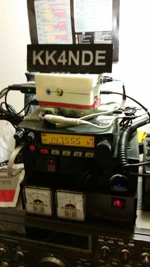
From top to bottom, this photo shows the original equipment I used:
- Raspberry Pi (with RS232 converter and USB sound card)
- Altoids tin with radio interface (PTT trigger, capacitor ground loop isolation, audio level adjustment)
- Yaesu FT-1900 radio (spare from upgrading my car radio)
- DIY cooling fan for the radio (stand 3D Printed)
- Samlex SEC-1235 power supply
Also pictured here is a Kenwood TS-930SAT which met an unfortuniate end when I sold it and was destroyed in shipping. They made good on the insurance but I'm still very sad to think all the hard work and money I put into it repairing the power supply, replacing capacitors, cleaning contacts, lubericating mechanisms, etc. getting it working really well just to have it smashed without hardly any use.
In any event, this setup worked well, I took it with me a couple times using my car's FT-8800 as the base to get squealch-detection and 70cm capability but it was a pain to set up every time.
My Hardware - Version 2
A friend suggested I should put it in a case to make it easier to transport and set up. A short time later, I was re-arranging my parts bins and noticed the Yaesu mobile radio was almost the same size as a PC CD-ROM drive. This gave me some ideas.
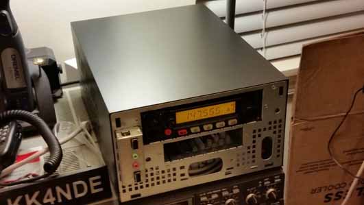
I obtained a mini-ITX computer case and did a test-fit of my radio in the CD-ROM bay, it was a perfect fit!
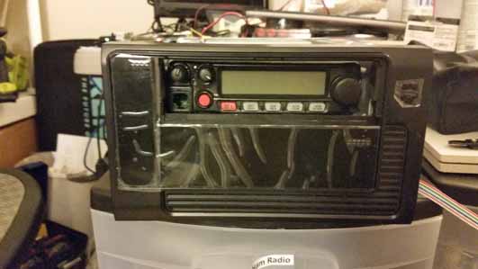
I then took my Dremel cutting tool to the plastic flap that covered the CD bay and made it so the front panel of the radio is accessible. This looks much better already!
 |
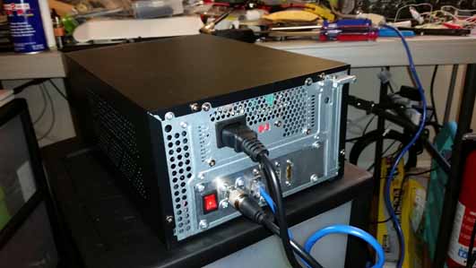 |
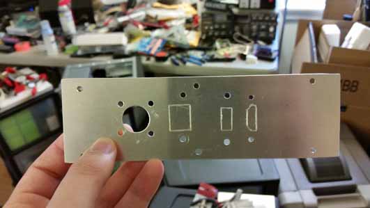
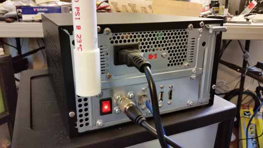
The next major hurdle was building a backplate for the case for all the required connections to route thru. Power was not an issue, I utilize the built-in mini-ITX power supply that came with the case, it provides more than enough 12V power for the radio and 5V power to run the Raspberry Pi and other electronics. For the backplate, I needed it to be easy to disconnect but also secure. I used a sheet of aluminum stock from the local hardware store to do this, I found it was easy to score with a disposable utility knife and then I could use "cold chisels" to punch out the approximate shape along the score line before filing it to an exact fit. In total I have cutouts for a power-switch (turns on the PSU), antenna (SO-239), Ethernet (RJ-45), USB (for WiFi/Cellular), and HDMI (for debugging).
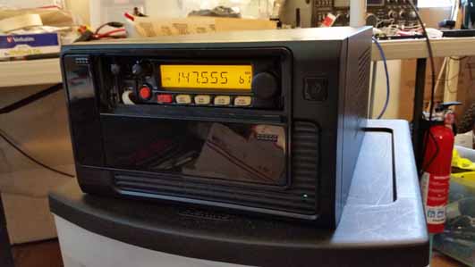
This was one of the first power-up tests I had, just to make sure it all worked. To start with, I used the Yaesu FT-1900 since I had it on hand but once I had a successful proof of concept I purchased a Yaesu FT-7900 as a drop-in upgrade to get dual band capability. most of the time it runs on 70cm now.
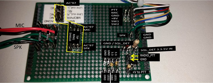
Here is a close-up of my custom breakout-board. It gives me pins I can reconfigure easily using jumper-wires for various connectors that I may need to interact with (front panel 3.5mm jacks, internal mic/speaker 3.5mm plugs, radio 6-pin mic plug, radio 2-pin audio plug, radio COS detect pin) as well as having a few of the componants I need (current-limiting resistors for the front-panel LEDs, voltage level-shifting zener/resister and transister). It's a bit large for what it needs to do but that makes it easier to work with. The voltage shifters are needed to interface 3.3V GPIO pins to the 5v/8v connections on the radio.
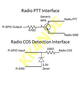
Note, since the Pi and radio share the same ground for power I only connect the ground on the side which requires an accurate reference. This means the radio-side for PTT (to ensure it's fully grounded) and the Raspberry Pi side for COS (to ensure the voltage is clamped to 3.3V to protect the GPIO on the ARM processor) This should help avoid ground-loops but may not matter. Alternatively you could use optoisolators to ensure good separation but this seemed simpler.
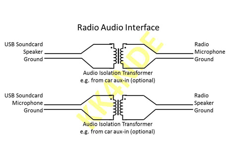
The audio interface is fairly straightforward, in order to eliminate any chance of ground-loop hum I used a couple car audio isolation transformers. This also seemed to help keep the audio from distorting as much. It's not neccesary - you could easily accomplish the same thing with careful adjustment of the volume controls and straight patch wires, inserting resistors, or using capacitors to couple the audio signal. The audio transformers I selected aren't any special impedence matching, they are just basic car aux-in ground-loop isolation filter transformers with 3.5mm plugs to match the soundcard.
Here's a quick overview of the wiring, what GPIO pin is going to what device. The "FP Header" is the PC case front panel motherboard header connectors. The jumpers lead over to my breakout board for intermediate circuitry, and the "Header" ones are going directly to another device's header (e.g. LCD)
| Function | Raspberry PI | Wire | Type |
| PTT_PIN | GPIO12 (out) | White | Jumper |
| CSQ_DET | GPIO06 (in) | Orange | Jumper |
| GROUND | GND | Black | Jumper |
| Svc Restart | GPIO04 (in) / GND | RESET_SW | FP Header |
| Shutdown | GPIO27 (in) / GND | PWR_SW | FP Header |
| PWR_LED | GPIO17 (out) | Green | Jumper |
| HDD_LED | GPIO18 (out) | Red | Jumper |
| LCD Power | +5V | Red | Header |
| LCD Ground | GND | Black | Header |
| LCD P4/Reg Sel | GPIO26 | Blue | Header |
| LCD P6/Enable | GPIO19 | Yellow | Header |
| LCD P11/Data4 | GPIO13 | Green | Header |
| LCD P12/Data5 | GPIO16 | Orange | Header |
| LCD P13/Data6 | GPIO20 | Gray | Header |
| LCD P14/Data7 | GPIO21 | White | Header |
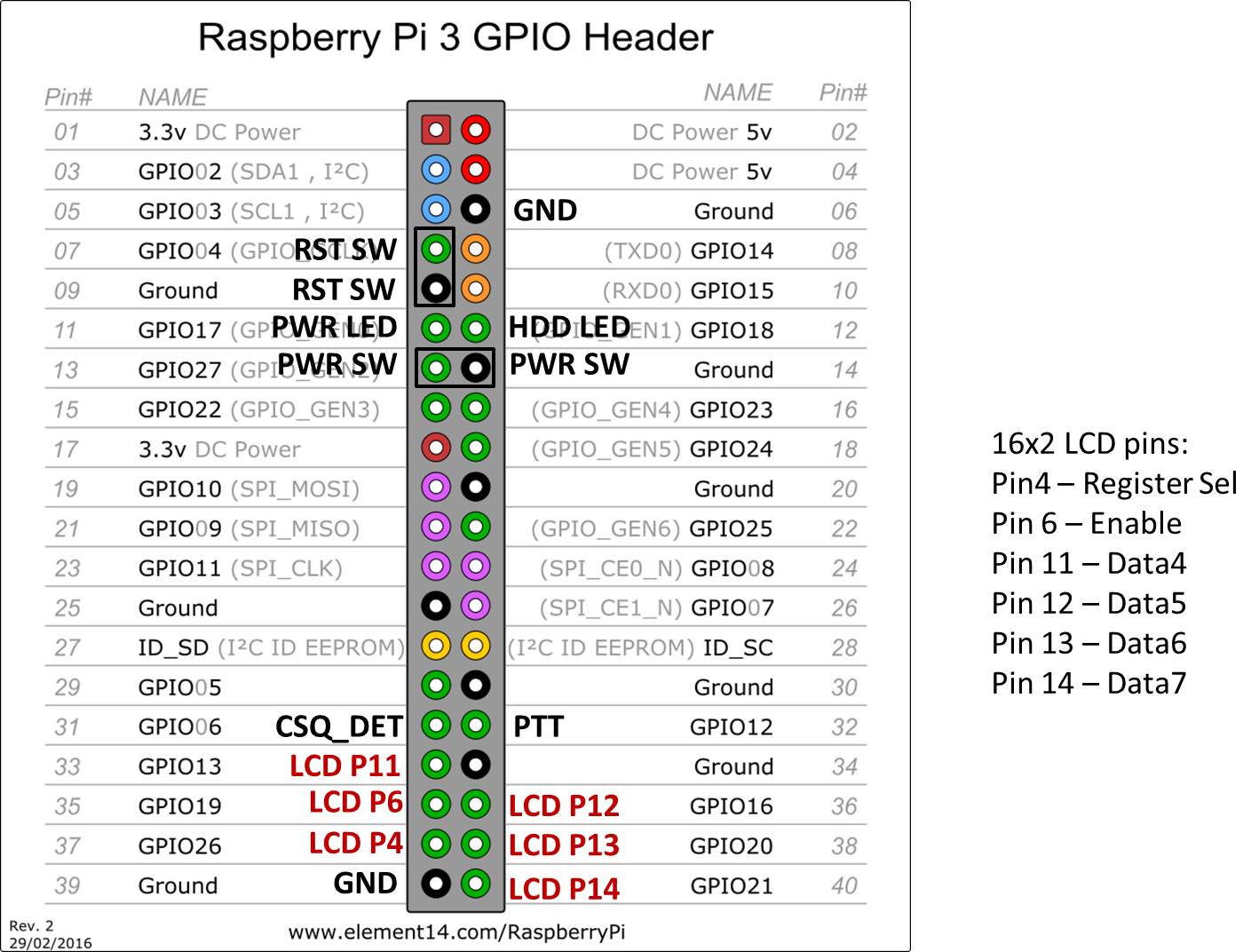
And this gives a visual diagram of the wires that connect up to the Pi, where they connect on the GPIO pins. I didn't show a couple of the power connections (e.g. 5V power feeds) because they can go anywhere and that should be the easy part. The LCD connections go directly thru a "wiring harness" to the front panel, the buttons are directly connected with the 2-pin motherboard headers coming from the front-panel, and everything else has jumpers to my custom breakout board for intermediate circuitry.
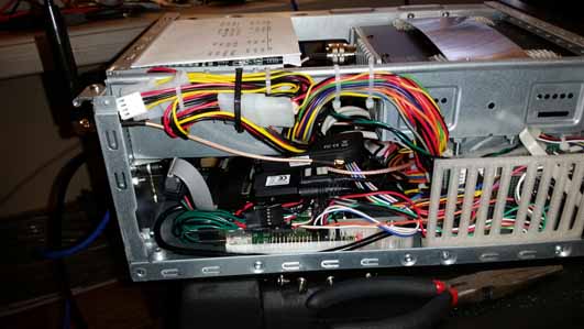
Here you can see the spaghetti of wires which connects everything together. The top left is the mini-ITX power supply that feeds everything. Below it is the Raspberry Pi that handles all the control logic, intefaced thru the homebrew breakout circuit board in the bottom right of this picture. Not shown are a pair of audio-isolation transformers (other side, behind the Raspberry Pi) and a 92mm cooling fan in the 3.5" drive bay to help air flow around the radio.
For the USB connectors (the mass of dark green wire in the lower left of the pic) on the PC case, I made adapters to plug the Ground and Data pins to the Raspberry Pi but ran the +5V and another Ground wire thru a 3A fuse to the +5V rail of the power supply. I also conneced a small USB hub inside the case the same way to run the soundcard, an RTL-SDR, and possibly another future device that I haven't figured out yet. By connecting the +5V to the power supply instead of the Pi's USB header this allows me to hot-plug devices (even high-current ones like WiFi dongles or cellular-modems) without the Pi rebooting or experienceing a brown-out. I connected the front-panel USB ports the same way (for charging stuff or using keyboard for debugging).
 |
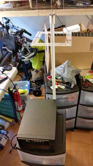 |
Next, I designed a mast for the antenna out of PVC pipe which is attached by a 3D printed adapter on each end. At the bottom, I have a couple screws which stick out of the metal chassis so the 3D printed part clips in with a bayonette style mount. At the top I have a 3D printed part which securely holds a PL-259 connector that is attached to the antenna. To start with, I had a quarter-wave ground plane antenna cut to resonate on the 70cm band, it was cheap and fast to build though ultimately got destroyed (crushed when stuff in the car shifted) while transporting it back home since it was fragile plain 14AWG copper wire hot-glued to a plastic form (to help keep the geometry correct) and didn't pack well.
  |
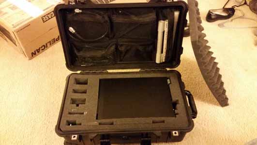 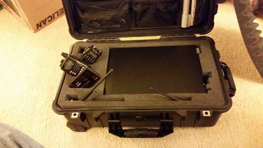  |
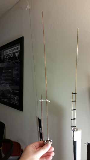
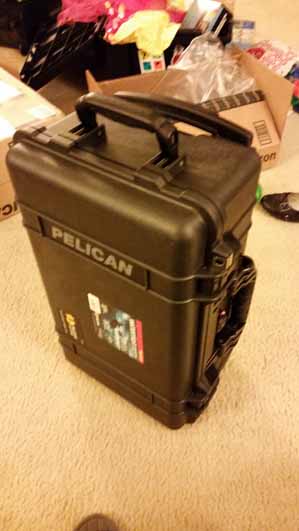
I've since upgraded the antenna to a J-pole variant based on these plans from KN9B's website. The new one is made of 1/8" brass rod with the spacers made out of 3D printed ABS plastic so it's much more durable, and being a J-pole type it packs much more compactly without risk of damage. Additionally, the PVC pipe mast is now cut into 3 sections connected by push-on pipe fittings so it can break down to fit in the case easily. I didn't measure my 2M SWR (although I may later) but I got it down around 1.5:1 on 446.1MHz where it normally is used. I've also got a Pelican 1510 case from Amazon as well as the optional lid organizer also on Amazon to protect everything when it's being transported. This also gives me a reliable way to pack the MiFi I use for internet on the go and my handheld radios so they don't get lost or damaged.
(click for full size)
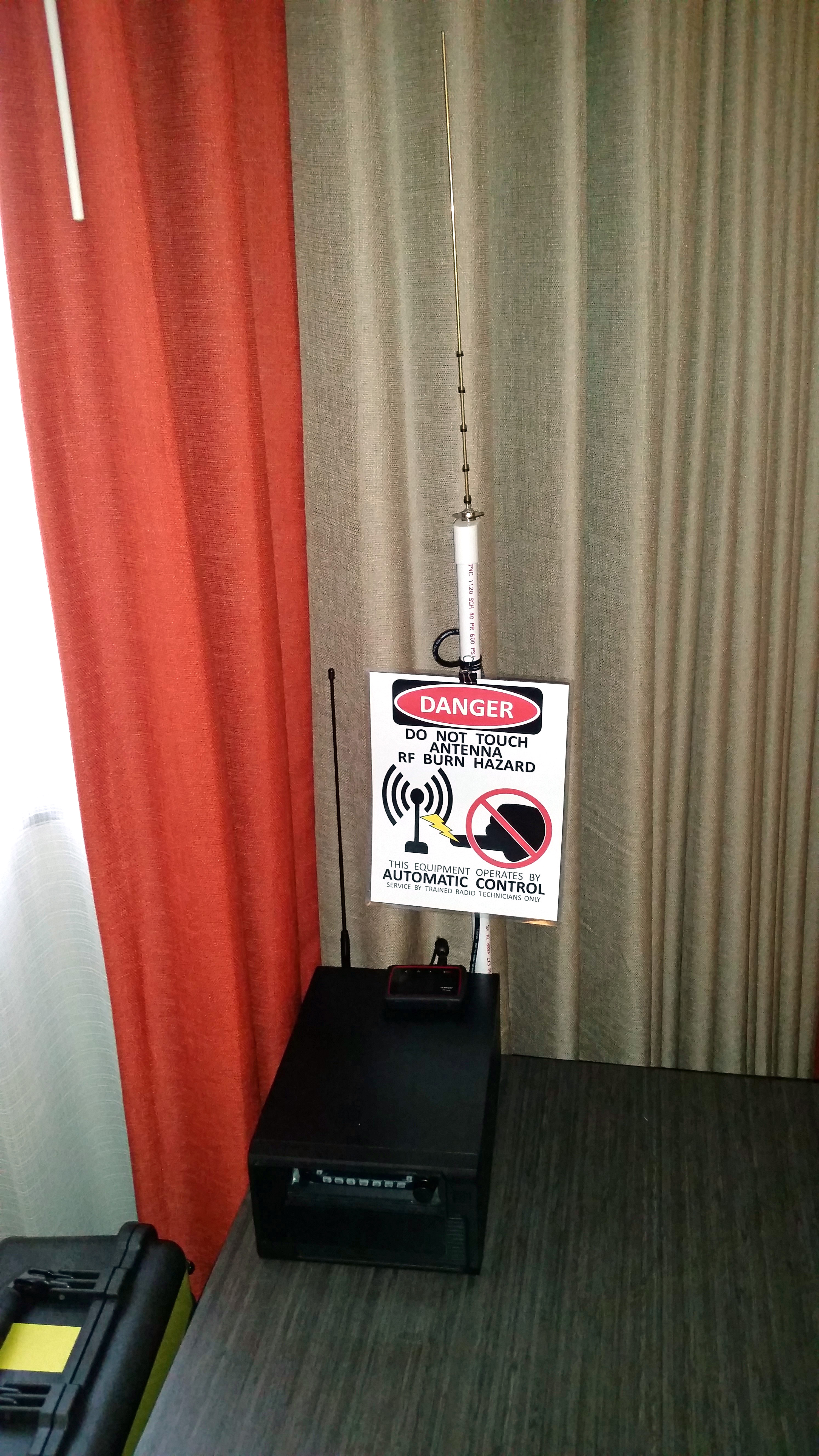
And here is the final result...on a trip where I hauled my setup all the way across the country as carry-on luggage set up in Reno, NV on a table in my hotel room. It performed very well and I had a pleasent QSO with another ham who was trying to set up an Echolink node with Svxlink himself and saw I had one to try and connect in. There you have it!
Additional update -- in December 2016 I enabled the svxlink QSO recorder functionality. This allows it to record the RF and Echolink audio, transcode it to highly-compressed 8-bit opus format and upload it to my website. The sample svxlink.conf in my GitHub page has been updated to reflect these features.
My Hardware - Version 3
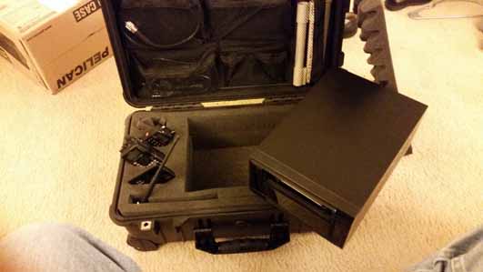
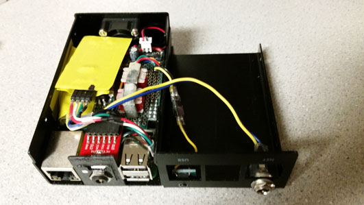
I started this revision of my Echolink node in March 2018. Overall I like how the v2 build came out but for some trips I could not justify the bulk for the amount of use it seemed to get. I also wanted to build something that could be turned into a portable digipeater using what I have learned for other projects. My plan was to build a Raspberry Pi and interface boards in a small case about the size of a deck of cards and then have a radio and power supply externally (so they could be packed separately e.g. to travel by air more easily). Overall this worked out well but there is a minor issue I have not yet worked out that 2-meter RF crashes the Raspberry Pi but it works fine with 70cm frequencies.
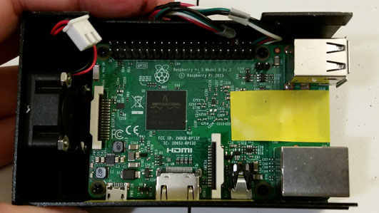
To begin with, I modified the Raspberry Pi by desoldering the middle USB ports, attaching wires out the bottom (to use those USB ports internally), and put header pins on the "run" reset pins for future use. I didn't have any proper electrical tape handy so I used yellow vynal tape to add extra insulation.
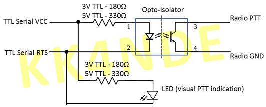
For this minimized version, I am using the same PTT interface that I used on my digipeater. Since I am intending to use it with a handheld that does not have COS output signaling I used VOX to detect received signals which simplifies my design.
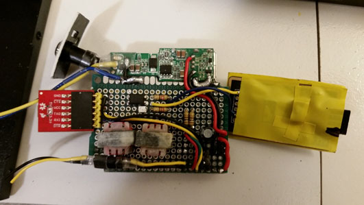
This is the top-view of the board I built to interface the Pi. You can see the top portion is a car-style USB power converter to provide a 5V power source from 12V external input. To the right is a USB serial FTDI board to provide the PTT signaling. The left is a USB-Serial UART that is connected to the Pi's UART debug ports, since I have no space for a LCD this will let me debug any issues by plugging in a micro-USB phone charger cable to my laptop "on the go". The middle is the circuitry with the Pi-Hat style connector at the bottom, 5V power rails middle-right, audio-isolation transformers lower middle, and opticoupler for PTT just above them. There are also a couple resistors for status LEDs tacked in. The yellow/blue wires at the top supply the 12V input to the power converter and the lower yellow/black wires go to a power switch to trigger graceful shutdown.
Here is the bottom view of the custom board - you can see the USB-soundcard tucked under the "hat" style PCB and the pins that connect to the Raspberry Pi header. I removed the USB port from the soundcard and replaced it with a header to save space. Many of them are not actually used but are for "future planning" and physical strength. You can see the 12v-USB power converter at the bottom and the USB-Serial debug as well as status LED on the left.
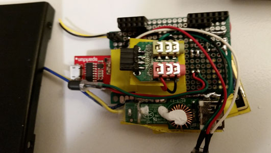
Now you can see everything connected up - the "Hat" plugged onto the Pi, the internal USB headers connected to the soundcard and FTDI board. There is also a 3D printed insert to help secure the debug microUSB port and radio connector. For the radio connector I used the same pinout as what is used in the Mobilinkd Bluetooth TNC so that I can use the same cables for either device. You can also see the 12V input jack and power button embedded in the top of the case. The power button is a small push-button soldered to a scrap of PCB epoxied to the case.
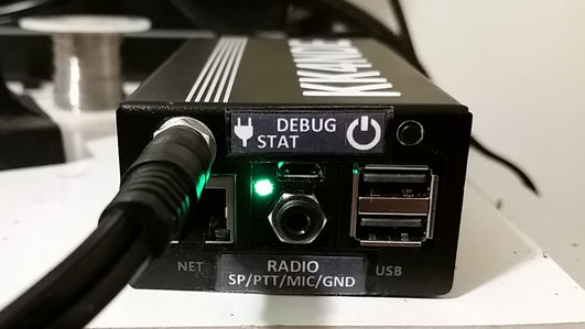
Here's the final product - with labeling affixed to the case.
I won't go over all the software - it's the same as my first two revisions with the exception of the PTT configuration line specifying a serial port instead of a GPIO pin.
(click for full size)
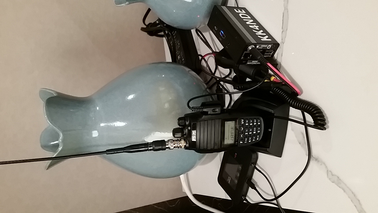
And here is the final result...on a trip where once again, I hauled my setup all the way across the country as carry-on luggage set up in Reno, NV on a table in my hotel room. Unfortuniately the internet seemed to be unreliable because something was jamming my Verizon 4G LTE Jetpack so it didn't work out well but otherwise it seemed to be a decent proof of concept. I could also benefit from a better "stand" to hold the radio upright, I used a charging base with a battery eliminator on the radio to power it but hopefully I will find or make something better for next time.
Other good references:
Here are a few other sites that have good references on how to set up Svxlink on a Raspberry Pi...I don't think any one way is "better" than another but I found in my experience I had to use a variety of different guides to get "just what I wanted". Unfortuniately I don't think I have the original site bookmarks I used to get my node working but here are a few good references I do have.
- GitHub: sm0svx/svxlink - InstallSrcHwRpi
- VR2XKP's blog: Life of RPi, using svxlink as Echolink node in RPi
- VR2XKP's blog: Echolink 2015 - SvxLink 14.08.1 as Echolink Node
- raspberry pi GEEK: GPIO Pinout - Rasp Pi 1 Model B+/Rasp Pi 2 Model B