APRS Digipeater + iGate
This project interfaces a Linux computer and radio transciever to create an APRS Digipeater and iGate that will upload packets to aprs.fi and support bi-directional communication.
System requirements:
- Reliable internet connection (for iGate, not required for Digipeater)
- Radio transciever
- Radio to PC interface (Audio and PTT/VOX)
- Debian based Linux computer(e.g. Ubuntu for desktop/laptop or Raspbian for Raspberry Pi) -- anything that uses "apt-get" to install software should be compatible with these scripts. If you use other distros, it is probably possible to tweak the commands but I don't have them ready-made.
- Soundcard with speaker & mic jacks to connect radio
My Hardware
Initial Setup
Current Setup
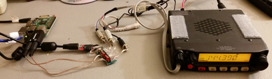
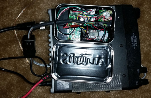
My initial configuration used a Yaesu FT-1900 connected to a Raspberry Pi2 Model B via a USB soundcard and DIY isolation/PTT interface. I have finally consolidated this down a bit more for "neatness" using a Raspberry Pi Zero-W which fits the whole controller and interface into an Altoids tin. This sits behind the FT-1900 to keep everything neat. Looking back I wish I'd used a full sized Raspberry Pi because the onboard wireless does not play nicely with WiFi and there is not enough free USB ports to add a wired network card without re-designing it. In future projects I will probably look at going to a full-sized Raspberry Pi in a metal case and modify it to allow for additional componants inside the case.
For a power supply I am using a X-Box gaming system power supply plugged into a modified Xbox-Slim adapter cord - the adapter cord is used to avoid cutting up the X-Box power supply, I can cut the adapter up and use the X-Box power plug. This is capable of providing 10-12 amps at 12V DC for the radio as well as 5V at 500-1000mA for the Raspberry Pi all in one neat sealed unit.
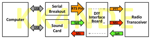
Here is a block diagram of how everything is connected:
Audio interface:
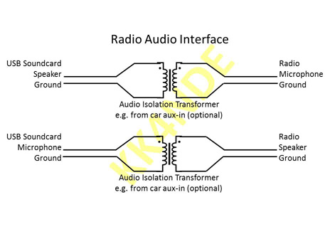
The audio interface is the same configuration I used for my Echolink node, simply connecting the audio thru audio isolation transformers. The only difference is this time I built my own "board" instead of buying pre-made in-line isolation transformers. This makes for a much smaller package.
For the PC side both microphone and speaker plugs I connected one wire to the "back" shield portion of the Tip-Ring-Shiled and the other to the "Tip". For the radio side, I connected to mono jacks that matched the speaker and an existing microphone adapter cable I had. I did not make any special considerations for "polarity" going in or out of the isolation transformer, I just hooked them up however it happened to be.
PTT interface:
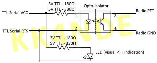
Once I got it working with a VOX-capable radio I built a simple circuit to trigger PTT using a Sparkfun CH340G USB Serial Breakout board. While the Raspberry Pi has the capability to use some GPIO pins for CTS/RTS I learned this has the side-effect of keying the radio during bootup until it "applies" the settings. I didn't like this so I went with an external USB chip in this configuration. Since the breakout board runs at TTL levels I had to invert the logic signal - I did this by connecting an optoisolator between VCC and RTS (instead of the usual RTS to GND) so that it activated when RTS went "low".
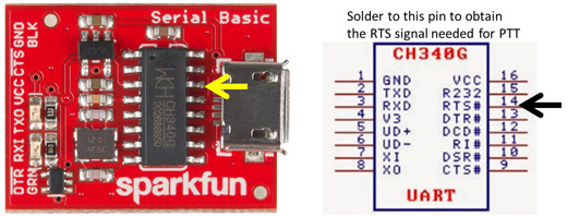
Unfortuniately I could not find a USB serial adpater that cost what I wanted to pay with CTS/RTS broken out (most have CTS/DTR, DTR is not useful for this) so I had to carefully solder an extra wire onto the chip to get the RTS pin that soundmodem uses for PTT signals.
TIP -- you can get a CH340G USB serial board MUCH cheaper from "fly by night" shops on eBay but shipping is slow; the Sparkfun one is available quickly in the US direct from Sparkfun or even faster on Amazon Prime for a couple more bucks!
Here is the completed PTT + Audio interface board:
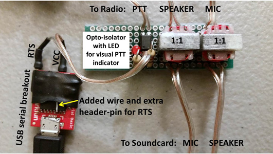
You can see the modified serial converter to the left, connected to the DIY circuit board. The perfboard contains the PTT circuitry and audio transformers.
Software
Description
There are two pieces of software - one to handle the packet modem encoding/decoding and the other to deal with the message handling. For the packet modem I used a program called "soundmoedm", this connects to a soundcard and serial port to interface the radio mic/speaker/PTT and provides a virtual network card device that other applications can interact with to send and receive messages. Part of the setup scripts I wrote also inject a rule for the Linux `iptables` firewall because we need to ensure that no general broadcast messages are unintentionally transmitted thru the packet modem over RF. The second piece of software is APRX which is an APRS digipeater and iGate application which handles the APRS traffic.
Configuration
Setup scripts: https://github.com/mmiller7/aprx-digipeater-setup
Troubleshooting
When you think everything is working you need to check and make sure it's working correctly - monitor the transmitter and ensure it is not sending any unexpected messages and that it is re-transmitting APRS messages it receives. I recommend finding another APRS or AX.25 decoder (or smartphone app) to verify what messages are going out over the air and that they look like what you expect. I found the most success was to start soundmodem first and then start aprx second. Logfiles should be in the /var/log directory, if you used my startup script from my install scripts soundmodem is in /var/log/soundmodem.log and /var/log/soundmodem.err. The logs for aprx should be in /var/log/aprx/aprx.log and /var/log/aprx/aprx-rf.log.